NAVIGATION EQUIPMENT AND METHODS
Compasses are the primary navigation tools to use when moving in an outdoor world where there is no other way to find directions.
TYPES OF COMPASSES
The lensatic compass is the most common and simplest instrument for measuring direction. It is discussed in detail below.
LENSATIC COMPASS
The lensatic compass ( Figure 1) consists of three major parts: the cover, the base, and the lens.
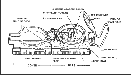
Figure 1. Lensatic compass.
- Cover. The compass cover protects the floating dial. It contains the sighting wire (front sight) and two luminous sighting slots or dots used for night navigation.
- Base. The body of the compass contains the following movable parts:
- The floating dial is mounted on a pivot so it can rotate freely when the compass is held level. Printed on the dial in luminous figures are an arrow and the letters E and W. The arrow always points to magnetic north and the letters fall at east (E) 90° and west (W) 270° on the dial. There are two scales; the outer scale denotes mils and the inner scale (normally in red) denotes degrees.
- Encasing the floating dial is a glass containing a fixed black index line.
- The bezel ring is a ratchet device that clicks when turned. It contains 120 clicks when rotated fully; each click is equal to 3°. A short luminous line that is used in conjunction with the north-seeking arrow during navigation is contained in the glass face of the bezel ring.
- The thumb loop is attached to the base of the compass.
- Lens. The lens is used to read the dial, and it contains the rear-sight slot used in conjunction with the front for sighting on objects. The rear sight also serves as a lock and clamps the dial when closed for its protection. The rear sight must be opened more than 45° to allow the dial to float freely.
COMPASS HANDLING
Compasses are delicate instruments and should be cared for accordingly.
- Inspection. A detailed inspection is required when first obtaining and using a compass. One of the most important parts to check is the floating dial, which contains the magnetic needle. The user must also make sure the sighting wire is straight, the glass and crystal parts are not broken, the numbers on the dial are readable, and most important, that the dial does not stick.
- Effects of Metal and Electricity. Metal objects and electrical sources can affect the performance of a compass. However, nonmagnetic metals and alloys do not affect compass readings. The following separation distances are suggested to ensure proper functioning of a compass:
| High-tension power lines …………………………………………. | 55 meters. |
| Car or truck ………………………………………….. | 18 meters. |
| Telegraph or telephone wires and metal fencing…………… | 10 meters. |
- Accuracy. A compass in good working condition is very accurate. However, a compass has to be checked periodically on a known line of direction, such as a surveyed azimuth using a declination station. Compasses with more than 3° + variation should not be used.
- Protection. If traveling with the compass unfolded, make sure the rear sight is fully folded down onto the bezel ring. This will lock the floating dial and prevent vibration, as well as protect the crystal and rear sight from damage.
USING A COMPASS
Magnetic azimuths are determined with the use of magnetic instruments, such as lensatic compass. The techniques employed when using the lensatic compass are as follows:
- Using the Centerhold Technique. First, open the compass to its fullest so that the cover forms a straightedge with the base. Move the lens (rear sight) to the rearmost position, allowing the dial to float freely. Next, place your thumb through the thumb loop, form a steady base with your third and fourth fingers, and extend your index finger along the side of the compass. Place the thumb of the other hand between the lens (rear sight) and the bezel ring; extend the index finger along the remaining side of the compass, and the remaining fingers around the fingers of the other hand. Pull your elbows firmly into your sides; this will place the compass between your chin and your belt. To measure an azimuth, simply turn your entire body toward the object, pointing the compass cover directly at the object. Once you are pointing at the object, look down and read the azimuth from beneath the fixed black index line (Figure 2). This preferred method offers the following advantages over the sighting technique:
- It is faster and easier to use.
- It can be used under all conditions of visibility.
- It can be used when navigating over any type of terrain.
- It can be used without removing eyeglasses.
Figure 2. Centerhold technique.
- Using the Compass-to-Cheek Technique. Fold the cover of the compass containing the sighting wire to a vertical position; then fold the rear sight slightly forward. Look through the rear-sight slot and align the front-sight hairline with the desired object in the distance. Then glance down at the dial through the eye lens to read the azimuth (Figure 3).
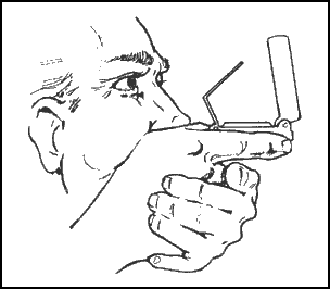
Figure 3. Compass-to-cheek technique.
- Presetting a Compass and Following an Azimuth. Although different models of the lensatic compass vary somewhat in the details of their use, the principles are the same.
- During daylight hours or with a light source:
- Hold the compass level in the palm of the hand.
- Rotate it until the desired azimuth falls under the fixed black index line (for example, 320°), maintaining the azimuth as prescribed (Figure 4).
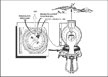
Figure 4. Compass preset at 320 degrees.
- Turn the bezel ring until the luminous line is aligned with the north- seeking arrow. Once the alignment is obtained, the compass is preset.
- To follow an azimuth, assume the centerhold technique and turn your body until the north-seeking arrow is aligned with the luminous line. Then proceed forward in the direction of the front cover’s sighting wire, which is aligned with the fixed black index line that contains the desired azimuth.
- During limited visibility, an azimuth may be set on the compass by the click method. Remember that the bezel ring contains 3° intervals (clicks).
- Rotate the bezel ring until the luminous line is over the fixed black index line.
- Find the desired azimuth and divide it by three. The result is the number of clicks that you have to rotate the bezel ring.
- Count the desired number of clicks. If the desired azimuth is smaller than 180°, the number of clicks on the bezel ring should be counted in a counterclockwise direction. For example, the desired azimuth is 51°. Desired azimuth is 51°¸ 3 = 17 clicks counterclockwise. If the desired azimuth is larger than 180°, subtract the number of degrees from 360° and divide by 3 to obtain the number of clicks. Count them in a clockwise direction. For example, the desired azimuth is 330°; 360°-330° = 30 ¸ 3 = 10 clicks clockwise.
- With the compass preset as described above, assume a centerhold technique and rotate your body until the north-seeking arrow is aligned with the luminous line on the bezel. Then proceed forward in the direction of the front cover’s luminous dots, which are aligned with the fixed black index line containing the azimuth.
- When the compass is to be used in darkness, an initial azimuth should be set while light is still available, if possible. With the initial azimuth as a base, any other azimuth that is a multiple of three can be established through the use of the clicking feature of the bezel ring.
| NOTE: | Sometimes the desired azimuth is not exactly divisible by three, causing an option of rounding up or rounding down. If the azimuth is rounded up, this causes an increase in the value of the azimuth, and the object is to be found on the left. If the azimuth is rounded down, this causes a decrease in the value of the azimuth, and the object is to be found on the right. |
- Bypassing an Obstacle. To bypass enemy positions or obstacles and still stay oriented, detour around the obstacle by moving at right angles for specified distances.
- For example, while moving on an azimuth of 90° change your azimuth to 180° and travel for 100 meters. Change your azimuth to 90°and travel for 150 meters. Change your azimuth to 360°and travel for 100 meters. Then, change your azimuth to 90°and you are back on your original azimuth line (Figure 5).
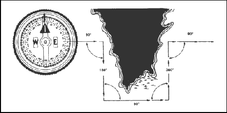
Figure 5. Bypassing an obstacle.
- Bypassing an unexpected obstacle at night is a fairly simple matter. To make a 90° turn to the right, hold the compass in the centerhold technique; turn until the center of the luminous letter E is under the luminous line (do not move the bezel ring). To make a 90° turn to the left, turn until the center of the luminous letter W is under the luminous line. This does not require changing the compass setting (bezel ring), and it ensures accurate 90° turns.
- Offset. A deliberate offset is a planned magnetic deviation to the right or left of an azimuth to an objective. Use it when the objective is located along or in the vicinity of a linear feature such as a road or stream. Because of errors in the compass or in map reading, the linear feature may be reached without knowing whether the objective lies to the right or left. A deliberate offset by a known number of degrees in a known direction compensates for possible errors and ensures that upon reaching the linear feature, the user knows whether to go right or left to reach the objective. Ten degrees is an adequate offset for most tactical uses. Each degree offset moves the course about 18 meters to the right or left for each 1,000 meters traveled. For example, in Figure 6, the number of degrees offset is 10. If the distance traveled to “x” in 1,000 meters, then “x” is located about 180 meters to the right of the objective.
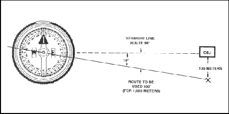
Figure 6. Deliberate offset to the objective.
ORIENTING THE MAP
The first step for a navigator in the field is orienting the map. A map is oriented when it is in a horizontal position with its north and south corresponding to the north and south on the ground. Some orienting techniques follow:
- Using a Compass. When orienting a map with a compass, remember that the compass measures magnetic azimuths. Since the magnetic arrow points to magnetic north, pay special attention to the declination diagram. There are two techniques used.
- First Technique. Determine the direction of the declination and its value from the declination diagram.
- With the map in a horizontal position, take the straightedge on the left side of the compass and place it alongside the north-south grid line with the cover of the compass pointing toward the top of the map. This procedure places the fixed black index line of the compass parallel to north-south grid lines of the map.
- Keeping the compass aligned as directed above, rotate the map and compass together until the magnetic arrow is below the fixed black index line on the compass. At this time, the map is close to being oriented.
- Rotate the map and compass in the direction of the declination diagram.
- If the magnetic north arrow on the map is to the left of the grid north, check the compass reading to see if it equals the G-M angle given in the declination diagram. The map is then oriented (Figure 7).
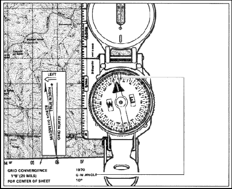
Figure 7. Map oriented with 11 degrees west declination.
- If the magnetic north is to the right of grid north, check the compass reading to see if it equals 360 degrees minus the G-M angle (Figure 8).
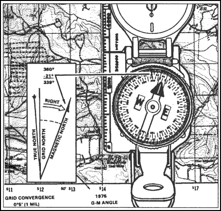
Figure 8. Map oriented with 21 degrees east declination.
- Second Technique. Determine the direction of the declination and its value from the declination diagram.
- Using any north-south grid line on the map as a base, draw a magnetic azimuth equal to the G-M angle given in the declination diagram with the protractor.
- If the declination is easterly (right), the drawn line is equal to the value of the G-M angle. Then align the straightedge, which is on the left side of the compass, alongside the drawn line on the map. Rotate the map and compass until the magnetic arrow of the compass is below the fixed black index line. The map is now oriented (Figure 9).
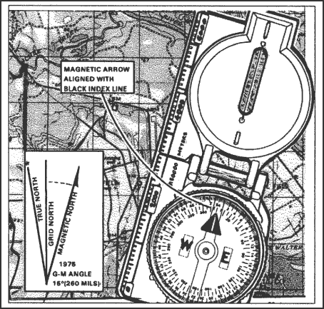
Figure 9. Map oriented with 15 degrees east declination.
- If the declination is westerly (left), the drawn line will equal 360 degrees minus the value of the G-M angle. Then align the straightedge, which is on the left side of the compass, alongside the drawn line on the map. Rotate the map and compass until the magnetic arrow of the compass is below the fixed black index line. The map is now oriented (Figure 10).
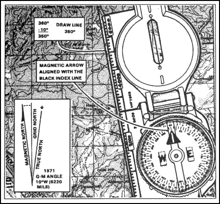
Figure 10. Map oriented with 10 degrees west declination.
| NOTE: | Once the map is oriented, magnetic azimuths are determined using the compass. Do not move the map from its oriented position since any change in its position moves it out of line with the magnetic north. Special care should be taken whenever orienting your map with a compass. A small mistake can cause you to navigate in the wrong direction. |
- Using Terrain Association. A map can be oriented by terrain association when a compass is not available or when the user has to make many quick references as he moves across country. Using this method requires careful examination of the map and the ground, and the user must know his approximate location (Figure 11).
Figure 11. Terrain association.
Mapping Level 4 Requirements:
- How to use a Lensatic Compass
- How to orient maps using all techniques in this level.